Dependable Assortment of Safety Relief Valve From Size 15NB TO 600NB (ANSI/ASA/ASME B16.5/PN/NPT)
FEATURE & BENEFITS


8100 Series Sefety Valve
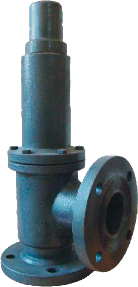 8100 Series Safety Valve Flanged (8100SV/8100SRV)
The 8100 Series of pressure relief valves provides a wide scope of design in both pressure and temperature ranges.
8100SV - Gas, Vapour or Steam Applications
8100SRV - Liquid Applications
| Inlet Sizes | 1" to 12" flanged |
| Inlet Rating (for flanged valves) |
ANSI Class 150 to 2500 |
| Outlet Sizes | 1" to 16" flanged |
| Outlet Ratings (for flanged valves) |
ANSI Class 150 and 300 |
| Orifice Sizes | Sixteen sizes - D through W |
| Set Pressure Range | 15 psig to 6250 psig |
| Temp. Range | -450°F to 1500°F |
| Materials | Carbon steel body with stainless steel trim is standard. Special alloys are available for specific applications. |
| Conforming Standards | API RP 520 TO 527 |
| Code | ASME Section III and VIII |
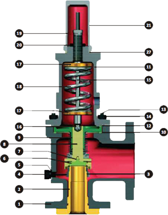
| S.No. | PART | MATERIAL |
| 1 | Body | ASTM A216 WCB/ CF8/ CF8M/CF3M |
| 2 | Nozzle | 410 SS /304 SS /316 SS /316L SS |
| 3 | Adjusting ring | 410 SS /304 SS /316 SS /316L SS |
| 4 | Adjusting ring pin | 410 SS /304 SS /316 SS /316L SS |
| 5 | Adjusting ring pin gasket | Soft iron/PTFE/Neoprene rubber/CAF |
| 6 | Disc | 410 SS /304 SS /316 SS /316L SS |
| 7 | Disc retainer | ringInconel X750 |
| 8 | Disc holder | 410 SS /304 SS /316 SS /316L SS |
| 9 | Guide | 410 SS /304 SS /316 SS /316L SS |
| 10 | Guide gasket | Soft iron/PTFE/Neoprene rubber/CAF |
| 11 | Bonnet | ASTM A216 WCB/ CF8/ CF8M/CF3M |
| 12 | Bonnet gasket | Soft iron/PTFE/Neoprene rubber/CAF |
| 13 | Stud | B7 Alloy steel |
| 14 | Fastener | B7 Alloy steel |
| 15 | Spindle | 410 SS /304 SS /316 SS /316L SS |
| 16 | Spindle retainer | Inconel X750 |
| 17 | Spring Washer | Carbon steel |
| 18 | Spring | Alloy steel, Tungsten, Spring Steel |
| 19 | Adjusting Screw | 410 SS /304 SS /316 SS /316L SS |
| 20 | Adjusting Screw locknut | 410 SS /304 SS /316 SS /316L SS |
| 21 | Screwed Cap | Carbon steel |
| 22 | Bellows | Inconel 625 LCF |
| Bellows ring & Flange | 410 SS /304 SS /316 SS /316L SS | |
| 23 | Bellows Gasket | Soft iron/PTFE/Neoprene Rubber/CAF |
This valve is the same as the conventional design except that a bellows has been added. When the bellows is installed, the educator tube is removed. Caution: It is important that the bonnet be vented to the atmosphere. A bellows is added to the conventional valve to deal with any of several situation.
- Back pressure entering the valve through the valve outlet is excessive or variable. If back pressure fluctuates with ±10% of a nominal value, a bellows is required. If a built up back pressure exceeds 10% of the set pressure or cold differential set pressure, a bellows must be used.
- If the entering fluid is slurry, highly viscous, or of a nature that it can enter the critical clearances between the guides/disc holders, protect that area with a bellows.
- If the fluid being handled is corrosive to the upper works of the valve, isolate the bonnet chamber through use of a bellows. Conventional valves can be easily converted to a bellows design or vice versa through the use of retrofit kits. All valves are balanced bellows designs, meaning that they fully compensate for the effects of back pressure.
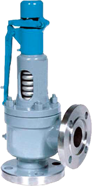
- Lever: Standard safety valves are generally fitted with an easing lever, which enables the valve to be lifted manually in order to ensure that it is operational at pressures in excess of 75% of set pressure. This is usually done as part of routine safety checks, or during maintenance to prevent seizing. The fitting of a lever is usually a requirement of national standards and insurance companies for steam and hot water applications. A standard or open lever is the simplest type of lever available. It is typically used on applications where a small amount of leakage of the fluid to the atmosphere is acceptable, such as on steam and air systems. Where it is not acceptable for the media to escape, a packed lever must be used. This uses a packed gland seal to ensure that the fluid is contained within the cap
- Open Bonnet: Unless bellows or diaphragm sealing is used, process fluid will enter the spring housing (or bonnet). The amount of fluid depends on the particular design of safety valve. If emission of this fluid into the atmosphere is acceptable, the spring housing may be vented to the atmosphere - an open bonnet. This is usually advantageous when the safety valve is used on high temperature fluids or for boiler applications as, otherwise, high temperatures can relax the spring, altering the set pressure of the valve. However, using an open bonnet exposes the valve spring and internals to environmental conditions, which can lead to damage and corrosion of the spring.
LIFT LEVER / OPEN BONNET
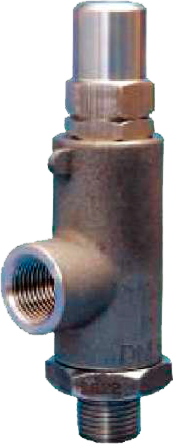
 9100 Series Safety Valve Screwed (9100SV/9100SRV)
These are screwed valves equivalent to 8100 series conforming to API Standards.
9100SV - For Gas and Vapour Applications
9100SRV - Liquid Application
| Inlet Sizes | 1" to 2-1/2" threaded |
| Outlet Sizes | 1" to 3” threaded |
| Set Pressure Range | 15 psig to500 psig |
| Temp. Range | -20°F to 800°F |
| Materials | Stainless steel base with stainless steel trim is standard. |
| Conforming Standards | API RP 520 TO 527 |
| Code | ASME Section VIII |
The Consolidated 8100 and 9100 series is compliant with the following codes and standards: - API 520, 526 and 527
APISTANDARD526-1995: Safety relief valves specified within this catalog comply with API standard 526 - Fourth Edition, 1995.
When ordering replacement valve that must comply with API Standard 526 - Third Edition,1984, contact the factory for verification of the correct replacement
Reliable performance and easy maintenance procedures are characteristics of this valve (when properly installed in suitable applications for its design). The parts are designed so that there is no blow down adjustment required when setting or testing the valve. This product is normally supplied with threaded inlet and outlet connections. Socket weld or flanged end connections are available as well. Product type designations change depending on connection sizes, orifice sizes, pressure range, and whether connections are male or female.
- 316 Stainless Steel
- 304 Stainless Steel
- Monel
- Hastelloy
- Alloy 20
- Carbon Steel
1000 SERIES
SAFETY VALVE BARSTOCK
 1000 Series Safety Valve Barstock (1000SV/1000SRV)
Threaded or Flange connection pressure relief valve conforming to manufacturer standards. The 1000 Series valves are designed and manufactured by Teleflo in compliance with ASME VIII. The Seat tightness, blow-down and capacity on all types of media meets the industry needs for over-pressure protection in chemical, petrochemical, refinery, power generation (nuclear and conventional) and other commercial applications.
| Inlet Sizes | 1/4" to 2" Threaded or Flanged |
| Outlet Sizes | 1/4" to 2-1/2" Threaded |
| Set Pressure Range | 15 psig to500 psig |
| Temp. Range | -20°F to 800°F |
| Materials | Carbon Steel or Stainless steel base with stainless steel trim is standard. |
| Code | ASME Section VIII |
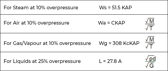
- A = Orifice area in Square inches
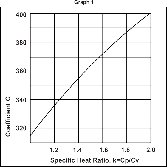
- C = Nozzle Constant depending on
Ratio of Specific Heats. (Refer Table A or Graph 1) - G = Specific Gravity (For Air 1 For Water = 1)
- K = Co-efficient of Discharge 0.96.
- M = Molecular Weight
- P = Set Pressure x 1. 1 + 14.7 PSIA.
- T = Inlet Temperature (°F + 460)
- Wa = Required Air Capacity in lbs / Hr.
- Wg = Required Gas / Vapour capacity in lbs Hr.
- Ws = Required Steam Capacity in lbs / Hr.
- L = Required Liquid Capacity in U.S.G.P.M.
- Kc = Combination Correction Factor
= 1.0, when a rupture disc is not installed
= 0.9, when a rupture disc is installed - Pd = Diff. Set Pressure in PSI
| k | C | k | C |
| 1.00 1.02 |
315 318 |
1.38 1.4 |
354 356 |
| 1.04 1.06 |
320 322 |
1.42 1.43 |
358 359 |
| 1.08 | 324 | 1.46 | 361 |
| 1.10 | 327 | 1.48 | 363 |
| 1.12 | 329 | 1.49 | 364 |
| 1.14 | 331 | 1.52 | 366 |
| 1.16 | 333 | 1.54 | 368 |
| 1.18 | 335 | 1.56 | 369 |
| 1.20 | 337 | 1.58 | 371 |
| 1.22 | 339 | 1.59 | 372 |
| 1.24 | 341 | 1.62 | 374 |
| 1.26 | 343 | 1.64 | 376 |
| 1.28 | 345 | 1.66 | 377 |
| 1.30 | 347 | 1.68 | 379 |
| 1.32 1.34 |
349 351 |
1.7 2 |
380 400 |

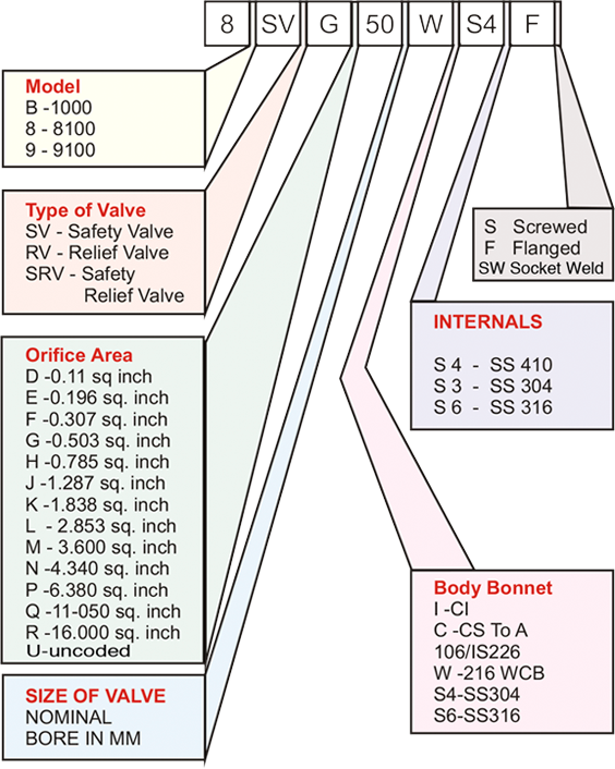
The size of the safety valve can be selected from Table B by calculating the area from the sizing formula and selecting the higher value of orifice area in the Table B.
* The sizing formula may vary depending on other factors
After the equipment installation or valve fitting, the following checks have to be made:
a) Verify that the safety valve corresponds to those one foreseen by the equipment Manufacturer on the ground of its final use. Check also all technical data written on the valve body and on the relative certificate that must be included in the equipment technical documentation.
b) Safety valves must be fitted in vertical position and in a place easy to be reached to facilitate maintenance and eventual rapid discharge actions.
c) In case of vessels filled with gas or steams and liquids, the relative safety valve must be fitted in the vessel area containing gas or steam, anyway as much as possible far from liquids.
d) Connection between vessel and safety valve has to be as short as possible and It must have a flow sectional area bigger than valve outlet area.
e) No narrowing or cutting device must be fitted between safety valve and vessel unless They are foreseen and stated by the equipment. Manufacturer directly and in compliance with the rules and laws in force.
f) Pipings and connections must be cleaned and free of deposits, chips and scales.
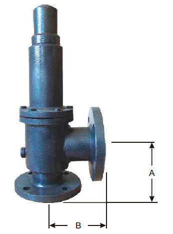
| ORIFICE DESIGNATION | SIZE (NB) | ANSI FLANGE CLASS | SELECTED ORIFICE AREA (Sq.Inches) |
CENTER TO FACE DIMENSIONS (Inches) |
|||
| INLET | OUTLET | INLET | OUTLET | A | B | ||
| D | 25 | 50 | 150 | 150 | 0.11 | 4 1/8 | 4 1/2 |
| 25 | 50 | 300 | 150 | 4 1/8 | 4 1/2 | ||
| 25 | 50 | 600 | 150 | 4 1/8 | 4 1/2 | ||
| 40 | 50 | 900 | 300 | 4 1/8 | 5 1/2 | ||
| 40 | 50 | 1500 | 300 | 4 1/8 | 5 1/2 | ||
| 40 | 80 | 2500 | 300 | 5 1/2 | 7 | ||
| E | 25 | 50 | 150 | 150 | 0.196 | 4 1/8 | 4 1/2 |
| 25 | 50 | 300 | 150 | 4 1/8 | 4 1/2 | ||
| 25 | 50 | 600 | 150 | 4 1/8 | 4 1/2 | ||
| 40 | 50 | 900 | 300 | 4 1/8 | 5 1/2 | ||
| 40 | 50 | 1500 | 300 | 4 1/8 | 5 1/2 | ||
| 40 | 80 | 2500 | 300 | 5 1/2 | 7 | ||
| F | 40 | 50 | 150 | 150 | 0.307 | 4 7/8 | 4 3/4 |
| 40 | 50 | 300 | 150 | 4 7/8 | 4 3/4 | ||
| 40 | 50 | 300 | 150 | 4 7/8 | 6 | ||
| 40 | 50 | 600 | 150 | 4 7/8 | 6 | ||
| 40 | 80 | 900 | 300 | 4 7/8 | 6 1/2 | ||
| 40 | 80 | 1500 | 300 | 4 7/8 | 6 1/2 | ||
| 40 | 80 | 2500 | 300 | 5 1/2 | 7 | ||
| G | 40 | 80 | 150 | 150 | 0.503 | 4 7/8 | 4 3/4 |
| 40 | 80 | 300 | 150 | 4 7/8 | 4 3/4 | ||
| 40 | 80 | 300 | 150 | 4 7/8 | 6 | ||
| 40 | 80 | 600 | 150 | 4 7/8 | 6 | ||
| 40 | 80 | 900 | 300 | 4 7/8 | 6 1/2 | ||
| 50 | 80 | 1500 | 300 | 6 1/8 | 6 3/4 | ||
| 50 | 80 | 2500 | 300 | 6 1/8 | 6 3/4 | ||
| H | 40 | 80 | 150 | 150 | 0.785 | 5 1/8 | 4 7/8 |
| 40 | 80 | 300 | 150 | 5 1/8 | 4 7/8 | ||
| 50 | 80 | 300 | 150 | 5 1/8 | 4 7/8 | ||
| 50 | 80 | 600 | 150 | 6 1/16 | 6 3/8 | ||
| 50 | 80 | 900 | 150 | 6 1/16 | 6 3/8 | ||
| 50 | 80 | 1500 | 300 | 6 1/16 | 6 3/8 | ||
| J | 50 | 80 | 150 | 150 | 1.287 | 5 3/8 | 4 7/8 |
| 50 | 80 | 300 | 150 | 5 3/8 | 4 7/8 | ||
| 80 | 100 | 300 | 150 | 7 1/4 | 7 1/8 | ||
| 80 | 100 | 600 | 150 | 7 1/4 | 7 1/8 | ||
| 80 | 100 | 900 | 150 | 7 1/4 | 7 1/8 | ||
| 80 | 100 | 1500 | 300 | 7 1/4 | 7 1/8 | ||
| K | 80 | 100 | 150 | 150 | 1.838 | 6 1/8 | 6 3/8 |
| 80 | 100 | 300 | 150 | 6 1/8 | 6 3/8 | ||
| 80 | 100 | 300 | 150 | 6 1/8 | 6 3/8 | ||
| 80 | 100 | 600 | 150 | 7 1/4 | 7 1/8 | ||
| 80 | 150 | 900 | 150 | 7 13/16 | 8 1/2 | ||
| 80 | 150 | 1500 | 300 | 7 3/4 | 8 1/2 | ||
| L | 80 | 100 | 150 | 150 | 2.853 | 6 1/8 | 6 1/2 |
| 80 | 100 | 300 | 150 | 6 1/8 | 6 1/2 | ||
| 100 | 150 | 300 | 150 | 7 1/16 | 7 1/8 | ||
| 100 | 150 | 600 | 150 | 7 1/16 | 8 | ||
| 100 | 150 | 900 | 150 | 7 3/4 | 8 3/4 | ||
| 100 | 150 | 1500 | 150 | 7 3/4 | 8 3/4 | ||
| M | 100 | 150 | 150 | 150 | 3.6 | 7 | 7 1/4 |
| 100 | 150 | 300 | 150 | 7 | 7 1/4 | ||
| 100 | 150 | 600 | 150 | 7 | 8 | ||
| 100 | 150 | 900 | 150 | 7 3/4 | 8 3/4 | ||
| N | 100 | 150 | 150 | 150 | 4.34 | 7 3/4 | 8 1/4 |
| 100 | 150 | 300 | 150 | 7 3/4 | 8 1/4 | ||
| 100 | 150 | 600 | 150 | 7 3/4 | 8 3/4 | ||
| 100 | 150 | 900 | 150 | 7 3/4 | 8 3/4 | ||
| P | 100 | 150 | 150 | 150 | 6.38 | 7 1/8 | 9 |
| 100 | 150 | 300 | 150 | 7 1/8 | 9 | ||
| 100 | 150 | 300 | 150 | 8 7/8 | 10 | ||
| 100 | 150 | 600 | 150 | 8 7/8 | 10 | ||
| 100 | 150 | 900 | 150 | 8 7/8 | 10 | ||
| Q | 150 | 200 | 150 | 150 | 11.05 | 9 7/16 | 9 1/2 |
| 150 | 200 | 300 | 150 | 9 7/16 | 9 1/2 | ||
| 150 | 200 | 600 | 150 | 9 7/16 | 9 1/2 | ||
| R | 150 | 200 | 150 | 150 | 16 | 9 7/16 | 9 1/2 |
| 150 | 200 | 300 | 150 | 9 7/16 | 9 1/2 | ||
| 150 | 250 | 300 | 150 | 9 7/16 | 10 1/2 | ||
| 150 | 250 | 600 | 150 | 9 7/16 | 10 1/2 | ||
| T | 200 | 250 | 150 | 150 | 26 | 10 7/8 | 11 |
| 200 | 250 | 300 | 150 | 10 7/8 | 11 | ||