
Providing Standard, Customized and heavy duty solution of Level indicator,Level transmitter and Level Switch with Quality Assurance
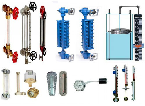
Gulf Oil & Gas International Welcomes you to explore the broad range of Industrial Field instruments, Process Instruments (Gauge,Level Indicators, Switches, Transmitters, FlowMeters), Test and Measurement Equipment, and Process Control Equipments of international brands( PI control Europe, Gems, ESI, Krohne, ABB, Honeywell, Dwyer, and others).We offer All Types Of Level indicators,Level transmitters, Level Switch. We are specialized in Standard as well as Customized solution of Level instruments. We have years of experience and a skilled team to understand and execute standard and customized solutions to all your requirements. We are committed to offer you the best quality at the most competitive price.
Level Indicator
Type Tubular: Reflex Transparent, Magnetic By-pass, Float and Board
Connection Connection: BSSP, NPT, Flanged etc
Material: PP, SS316, Carbon Seel etc
Tubular Level Indicator
Introduction
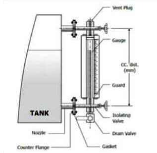
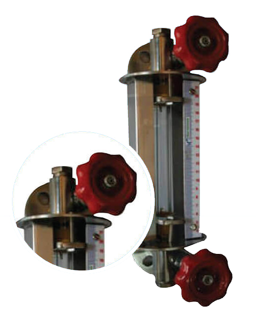
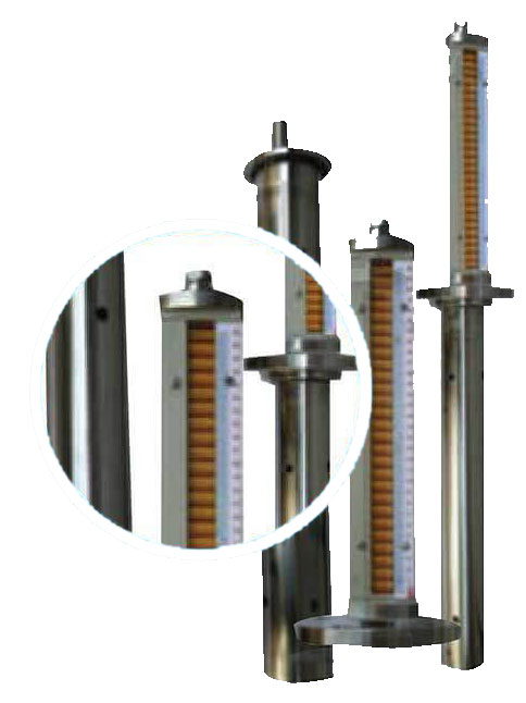
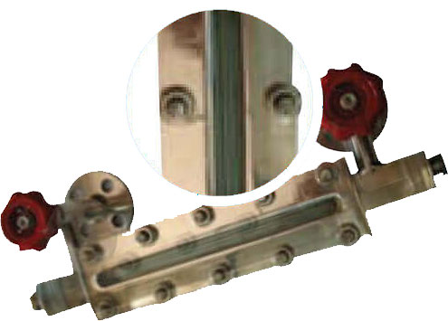
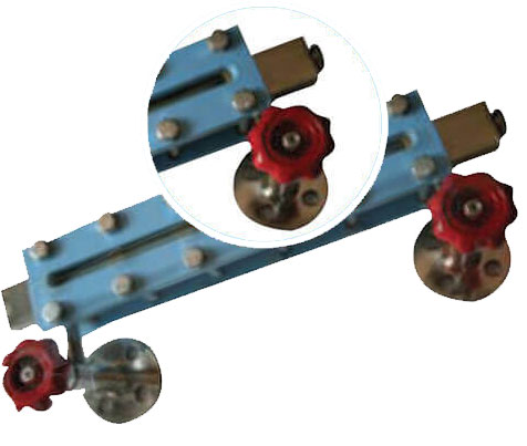
The PI controls Tubular Level Indicator (Side Mounted ) is reliable device for reading the level of the liquid in the tank can easily be observed. It is a simplest form of level indicator. These level indicators find wide application for level measurement in process tanks, batching tanks etc.
PrincipleThe Gauge is fitted between two end blocks through gland packings. The gauge is mounted parrallel to tank so as to form a close loop causing tank liquid to seek its level in gauge. Guards are provided in the form of tie - rods / c - channels round the gauge to protect it from accidential blows. End blocks have built - in isolating valve, drian and vent plug.
General data
- Glass Tube: Heavy Walled Borosillicate Glass Side H-19 / 16 Teflon
- End Block MOC: CS / SS 304 / SS 316 / PP / PVDf
- Protective Channel: C.S. Rectangle Channel Box with Powder Coated
- Packing: Teflon
- Connection: Flanged ASA
- Valve: CS / SS 304 / SS 316 / PP / PVDF
Design Data
- Mounting: Side Operating
- Pressure: Up to 15 kg/cm2
- Operating Temperature: Up to 100 C Up to 4 Meters
- Process Connection: Flanged or Screwed
- C-C Distance ( +- 3 mm ): Up to 4000 mm ( More 4000 mm Please consult Factory )
- Visibilty: C-C Distance - 150 mm
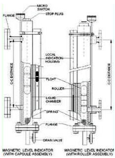
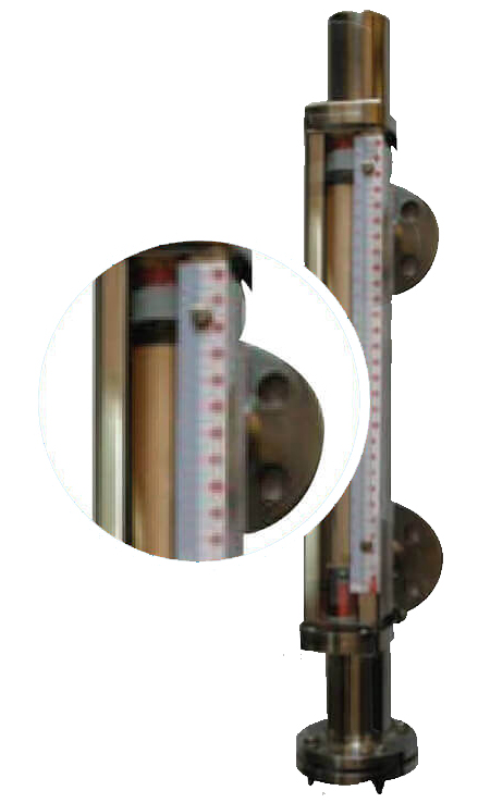
Magnetic Level Gauge- Magnetic Follower Capsule
Introduction
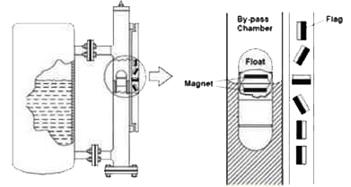
The By-Pass Level indicator is installed outside of a vessel or tank. The liquid level in the tank can easily be observed from the change of the flag color. Optional devices of magnetic switch and level transducer can be added for electrical signal output and level transmitting.
PrincipleThe By-Pass indicator utilizes hydrostatic principle to show the liquid level in the tank. A float with a magnet inside rises and drops accordingly to the liquid level change. Magnetic flags will flip as float passes through to indicate level based on magnetic attraction method.
General data
- Density: from 0.7 g/cm3
- Precision for Interface or Density: from +- 0.01 g/cm
- Measuring Error: +- 10 mm
- Viscosity: Max 1000mPas
- Connection: Weld End (Standard) /Flanges DIN and ANSI
- Weight: Basic 7Kg
Design Data
- Mounting: Top or Side
- Operating Pressure: Up to 50 Kg/cm2
- Operating Temperature: -20 to 400 °C
- Process Connection: Flanged or Screwed
- CC Distance (+- 3mm): Upto 600 mm
- Flag Display Length: Upto 600mm
- Specific Gravity: 0.7 (Min.)
- Indicator Roller: Metallic
Optional Accessories
Magnetic Level Switches
Reed switches or electrical snap (magnetic pendulum switch) may be mounted on the rail of the level gauge to be activated at high/low levels. The number of switches is only limited by the length of indication rail and the switches can be mounted on the left and right side of the rail. Mounting the level switches is a very easy task.
Magnetic Level Transmitter
The analogue transmitter mounts directly to the side of the gauge chamber, providing a continuous 4-20mA output signal proportional to the liquid level with an accuracy of +-3mm. Using simple and reliable reed switches surface mounted to printed circuit board. The transmitter can be equipped with a local indicator to show the level height in a length scale or indicate the percentage of the total height or the tank volume.
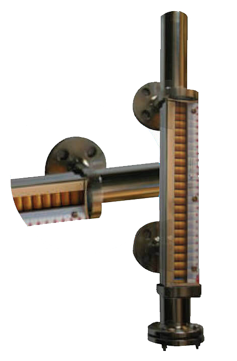
Magnetic Level Gauge - Bicolour Rotating Flappers
Introduction
The By-Pass Level indicator is installed outside of a vessel or tank. The liquid level in the tank can easily be observed from the change of the flag color. Optional devices of magnetic switch and level transducer can be added for electrical signal output and level transmitting.
PrincipleThe By-Pass indicator utilizes hydrostatic principle to show the liquid level in the tank. A float with a magnet inside rises and drops accordingly to the liquid level change. Magnetic flags will flip as float passes through to indicate level based on magnetic attraction method.
General data
- Density: from 0.7 g/cm3
- Precision for Interface or Density: from +- 0.01 g/cm3
- Measuring Error: +- 10 mm
- Viscosity: Max 1000mPas
- Connection: Weld End (Standard) /Flanges DIN and ANSI
- Weight: Basic 7Kg
Design Data
- Mounting: Top or Side
- Operating Pressure: Up to 50 Kg/cm2
- Operating Temperature: -20 to 400 °C
- Process Connection: Flanged or Screwed
- CC Distance (+- 3mm): Upto 600 mm
- Flag Display Length: Upto 600mm
- Specific Gravity: 0.75 (Min.)
- Indicator Roller: Metallic
Optional Accessories
Magnetic level switches
Reed switches or electrical snap (magnetic pendulum switch) may be moulded on the rail of the level gauge to be activated at high/low levels. The number of switches is only limited by the length of indication rail and the switches can be mounted on the left and right side of the rail. Mounting the level switches is a very easy task.
Magnetic level Transmitter
The analouge transmitter mounts directly to the side of the gauge chamber, providing a continuous 4-20mA output signal proportional to the liquid level with an accuracy of +-3mm. Using simple and reliable reed switches surface mounted to printed circuit board. The transmitter can be equipped with a local indicator to show the level height in a lenght scale or indicate the percentage of the total height or the tank volume.
Top Mounted Magnetic Level Indicator
Introduction
The By-Pass Level indicator is installed outside of a vessel or tank. The liquid level in the tank can easily be observed from the change of the flag color. Optional devices of magnetic witch and level transducer can be added for electrical signal output and level transmitting.
PrincipleThe By-Pass indicator utilizes hydrostatic principle to show the liquid level in the tank. A float with a magnet inside rises and drops accordingly to the liquid level change. Magnetic flags will flip as float passes through to indicate level based on magnetic attraction method.
General data
- Density: from 0.7 g/cm3
- Precision for Interface or Density: from +- 0.01 g/cm3
- Measuring Error: +- 10 mm
- Viscosity: Max 1000mPas
- Connection: Weld End (Standard) /Flanges DIN and ANSI
- Weight: Basic 7Kg
Design Data
- Mounting: Top or Side
- Operating Pressure: Up to 50 Kg/cm2
- Operating Temperature: -20 to 400 °C
- Process Connection: Flanged or Screwed
- CC Distance (+- 3mm): Upto 600 mm
- Flag Display Length: Upto 600mm
- Specific Gravity: 0.7 (Min.)
- Indicator Roller: Metallic
Optional Accessories
Magnetic level switches
Reed switches or electrical snap (magnetic pendulum switch) may be moulded on the rail of the level gauge to be activated at high/low levels. The number of switches is only limited by the length of indication rail and the switches can be mounted on the left and right side of the rail. Mounting the level switches is a very easy task.
Magnetic level Transmitter
The analogue transmitter mounts directly to the side of the gauge chamber, providing a continuous 4-20mA output signal proportional to the liquid level with an accuracy of +-3mm. Using simple and reliable reed switches surface mounted to printed circuit board. The transmitter can be equipped with a local indicator to show the level height in a length scale or indicate the percentage of the total height or the tank volume.
Reflex Level Indicator
Introduction
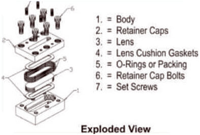
The PI Controls Reflex Level indicates are designed for safe and positive visual indication of liquid level in vessels under high pressure and temperature conditions.
PrincipleThe PI Controls Reflex flat glass level indicates has precision moulded prismatic grooves cut on inner surface, which comes in contact with liquid. Light striking on glass portion covered by liquid is reflected (absorbed) making this portion appear BLACK, whereas glass portion covering vapour space reflects light making it appear SILVERY - WHITE. Thus a sharp clear line marks the liquid, eliminating all possibilities of erros in reading.
Gauge Classification
- Gauge Glass: Tempered soda ash / Borosilicate (30W x 17 mm Thk) / Tempered Borosilicate (34W x 17mm Thk)
- Cushion / Gasket: CAF, CNAF, PTFE, Ss304 Spiral wound with Graphite Filler & Ss316 Spiral wound with Graphite Filler.
- Body (Liquid Chamber): CS, ASTM A-105, SS304, SS316 or PP (CS Reinforced)
- Cover Plate: CS, ASTM A-105, SS304, SS316 or FRP
- Bolts: CS, SS304 or A 193 Gr. B7
- Nuts: CS, SS304 or A 193 Gr. B7
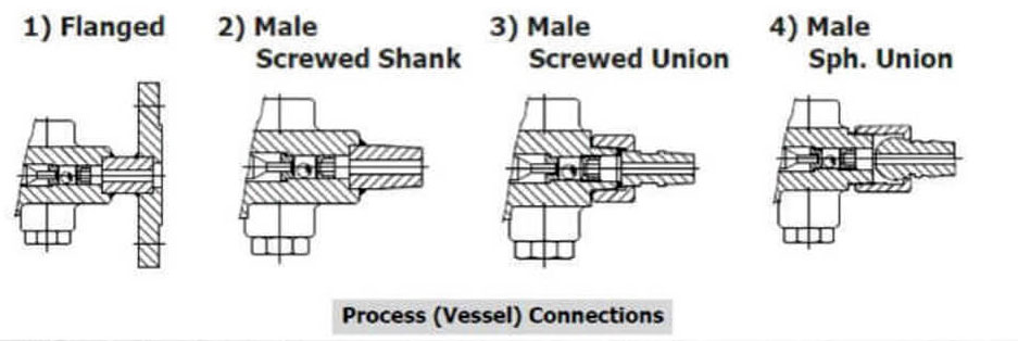
- Process Connection Orientation: Rear / Rear or left / Left or Right /Right or Veritical / Vertical
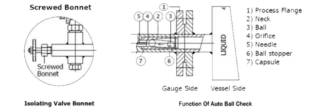
- Isolation Valves: Offset needle valve x auto ball check x screwed bonnet (85 Kg /cm2) / Union bonnet (165 kg/cm2) / Bolted bonnet (210 kg/cm2)
- Vent: 1/2” NPT (BSP for PP / TEFLON MOC) plug / valve (Ball, Needle, Diaphragm, Globe, Gate as required)
- Drain: 1/2” NPT (BSP for PP / TEFLON MOC) plug/ valve (Ball, Needle, Diaphragm, Globe, Gate as required)
- Calibrated Scale: Polycarbonate / SS304 / Aluminum
- Special Features:
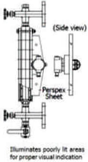
- Frost Free extn: Perspex sheild with extension of 30 mm.
- Jacketing: Enclosure Cast AI, WP IP 65 or Ex-Proof Gr. IIA & IIB or IIC
- None: Longer C-C Distance are provided in 2 chambers coupled with flange coupler
Transparent Level Indicator
Introduction
The PI Controls Transparent Level indicates are designed for safe and positive visual indication of liquid level in vessels under high pressure and temperature conditions.
PrincipleThe PI Controls Transparent flat glass level indicators is a clear glass for visual indication and specially for interface services or where the liquidis dirty or viscous. Light striking on glass portion covered by liquid is reflected (absorbed ) making this portionappear BLACK, whereas glass portion covereing vapoour space reflects light making it appear - WHITE athus a sharp clear line marks the liquid, eliminating all possibilities of error in reading.
Gauge Classification
- Low Pressure: 30 Kg/cm2
- Medium Pressure: 65 Kg/cm2
- High Pressure: 100 Kg/cm2
- Gauge Glass: Tempered soda ash / Borosilicate ( 30W x 17 mm Thk ) / Tempered Borosilicate ( 34W x 17mm Thk )
- Cushion / Gasket: CAF, CNAF, PTFE, Ss304 Spiral wound with Graphite Filler & Ss316 Spiral wound with Graphite Filler.
- Body ( Liquid Chamber ): CS, ASTM A - 105, SS304, SS316 or PP ( CS Reinforced)
- Cover Plate: CS, ASTM A-105, SS304, SS316 or PP ( CS Reinforced)
- Bolts: CS, SS304 or A 193 Gr. B7
- Nuts: CS, SS304 or A 193 Gr. B7 Process Connection Orientation: Rear / Rear or left / Left or Right /Right or Veritical / Vertical
- Isolation Valves: Offset needle valve x auto ball check x screwed bonnet ( 85 Kg /cm2 ) / Union bonnet ( 165 kg/cm2) / Bolted bonnet ( 210 kg/cm2 )
Welded Pad Type Level Indicator
Introduction
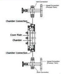
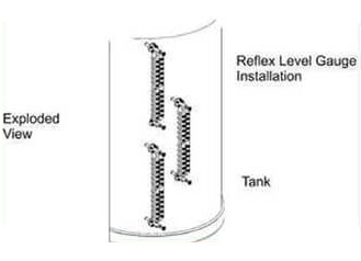
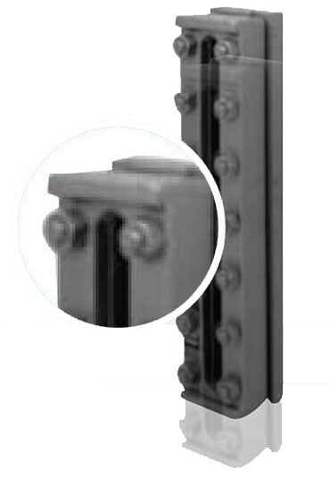
The Welded Pad Type Level indicators are used where conventional gauge and valve construction is impractical because of solid matter in suspension, under conditions where the thermal error caused by piping to a gauge glass cannot tolerate or where space requirements suggest their use. Included are applications involving high vibration, highly viscous liquids or liquids with considerable amounts of solid...
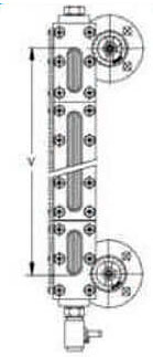
PrincipleThe Welded Pad Type Level Indicator unit is designed to be welded directly onto a tank or other liquid containing vessel. Standard Liquid Level Gauge units are furnished with a flat bottom. Upon request the unit can be machined with a cylinderical radius to match the contour of the vessel.
The Liquid Level Gauges are avilabe in single or multiple types.
Gauge Classification
| Body Material | Gasket Material | Pressure | Temperature |
| Carbon Steel | EPDM | 20 Kg/cm2 | -25 °C to 150 °C |
| TFE | 20 Kg/cm2 | -25 °C to 150 °C | |
| Viton | 20 Kg/cm2 | -25 °C to 150 °C | |
| Silicone | 20 Kg/cm2 | -25 °C to 150 °C | |
| AISI 316 SS | EPDM | 40 Kg/cm2 | -50 °C to 150 °C |
| TFE | 40 Kg/cm2 | -40 °C to 240 °C | |
| Viton | 40 Kg/cm2 | -25 °C to 150 °C | |
| Silicone | 40 Kg/cm2 | -55 °C to 240 °C |
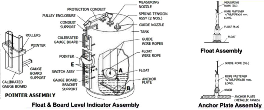
Float & Board Level Indicator
Introduction
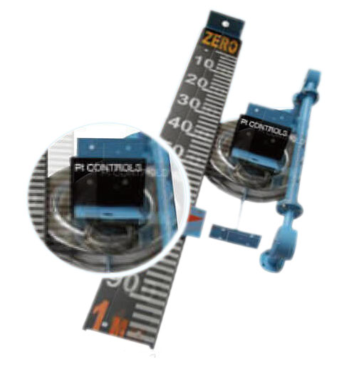
The Float Board Level Indicators are designed for an accurate, reliable and trouble free float operated technique used in large non-pressurized storage tanks.
Principle1) Guided & Direct Indication
The Float & Board Level Indicators consits of a float connected to a pointer through a rope via a set of pulleys. The pointer glides over a calibrated gauge board, positioned parallel to the tank. The float accurately follows liquid level variations in vertical direction. The horizontal float movement is restricted by two guide wires firmly anchored to tank bottom. As such, the pointer in the TOP POSITION when tank is EMPTY and in BOTTOM POSITION when FULL
2) Unguided and Direct Indication
Construction for this type of Float & Board Level Indicators is smiliar to the above, except guide wires are not provided, as the horizontal float movement is negligible.
Gauge Classification
- Measuring Range: 7.5 mtrs. with ø200mm float
- Float: Upto 20 mtrs. with ø350 mm
- Calibrated Gauge Board: SS316 x ø200 & ø350mm
- Low Pressure: PP x ø200mm
- Medium Pressure: 6” wide x AI white powder coating with black graduations and numericals
- Least count: 5mm
- Maximum Temperature: 80 °C ( PP) / 150 °C (SS)
- Maximum Pressure: 5Kg/cm2
- Float Wire Rope: Ø1.6mm x SS 316 / SS 304 multistrand)/ Ø3mm xPP (multistrand) Guide Wire Rope: Ø 1.6mm x SS 316 / SS 304 (multistrand) / Ø3mm xPP (multistrand)
- Installation: Grounded Level Tank / Underground Tank ( sump ) / Overhead Tank
- Specific Gravity of Fluid: 0.75
- Connection Pipe: Carbon Steel Powder Coated
- Direct: Powder coated Red CI Pointer with Nylon Rollers to provide super smooth movement along gauge\ board. Pointer Tip indicates “Level”
- Follow Magnet: Red Capsule moving inside indicator tube. White annular line on capsule indicates ‘Level’.
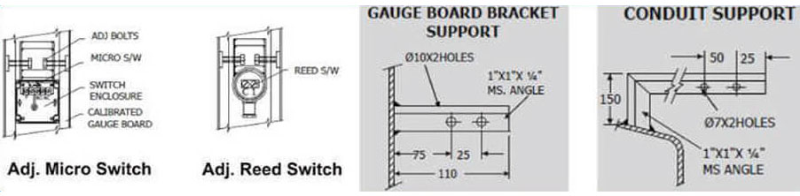
- Pulley Assemblies Cadmium Plated Steel Pulley with PTFE bush and SS shaft housed in weather proof CI enclousure (2 Nos. )
- Horizontal Limb: GI pipe 25NB x 650 to 1100mm ( adjustable)
- Vertical Limb: GI pipe 25NB x 285mm & 195 mm long
- Spring Tensioner Assy’s: Cadmium Plated Steel Spring Housed In CI enclosure
- Process Connections: 3/4” NB, BS-10T ‘D’ flange
- Anchor Plate: SS304 / SS316 plate ( 50 mm x 6mm thick )
- Gauge Board Brackets: Powder coated MS
- Wire Fastners: SS304 / SS316
- Seal Pot: For Tanks with vapour pressure upto 600 mm WC orrosive fumes
- Adjustable S/W: Reed S/W - 40VA (N/O), 60VA ( C/O), Micro S/W - 5A, 230 VAC ( C/O)
- Note: Custom made assemblies can be provided for specific applications
Magnetic Level Switch
Type Miniature, Cable Float, Side Mounted, Top Mounted
Connection BSSP, NPT, Flanged etc
Material PP, SS316, etc
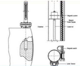
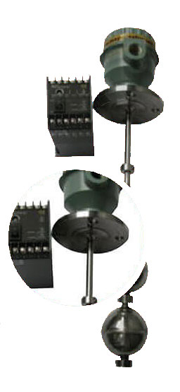
Top Mounted Magnetic Level Switch
Introduction
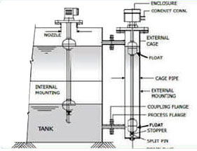
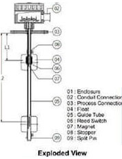
The Top Mounted Level Switch is an established and reliable technique in industry for single or multiple liquid level sensing and control in open or pressurized vessels. It offers trouble free service in conductive and non- conductive liquids under widely varying temperatures, pressure, liquid viscosity and corrosive conditions, Besides it provides high repeatability, and effects of shocks or variations are minimal.
PrincipleThe Top Mounted Level Switch has a simple & study construction consisting of a float and guide tube, made of nonmagnetic material to achieve un-distributed magnetic flux. The float has a magnetic system within it and moves freely along the guide tube, which contains glass encapsulated hermetically sealed reed switches, located at preset positions. Float follows liquid level and magnetically actuates reed switch at preset positions to give a change over contact. Single or multiple switching is effected through single or multiple floats as required by application. Mounted internally or extremely through a external chamber. External mounting is adopted to overcome limited space within the tank or where mechanical devices like stirrers operate or where isolation tank is required for regular servicing. It can be mounted vertically from top. The level switch can be wired directly in series to operate electrical loads like audio or alarm, annunciation, mimic indication, which match the low swtiching capacity of reed contacts. However, high loads like contactor, solenoid or motorised valve should be connected thorugh a level controller to prevent overloading by surge or inrush current and isolate reed contacts from the electrical power system, to ensure their long life.
Specification
- Installation: Outdoor/Indoor
- Mounting: Top
- Terminal Enclosure: Cast Aluminium, Weather proof to IP 66 or Ex - proof to Gr. IIA & IIB or IIC
- Conduit Connection: 1/2” BSP ( F) with 1/2 “ BSP (M) conduit
- MOC of Guide Tube: SS316, PP, SS316 with PVDF coated
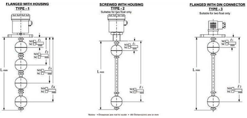
- No. of Floats: Single or multiple ( Maximum of 4)
- MOC of Floats: SS316, PP or PVDF
- Size of Floats: Ø28 , Ø41,60,75,90mm for Ss316,50,63,90mm for PP and 60, 75 & 90mm for PVDF
- Process connections: Flanged with Housing, Screwed with Housing or flanged with DIN Connector
- Min.Specific Gravity: 0.7 (minimum)
- Switch Type: Reed Switch
- Switch Rating: 0.5A/250 VAC
- Switch Differential: Fixed ( 10 +- 5mm)
- Housing Material: Die - Cast Alumiinuim
- Ingress Protection: IP65
- MOC of Wetted Parts: AISI 316 SS
- Accuracy: +_2mm
- Repeatability: +_1mm
- Load: Resistive or inductive
- Insulation: 100 Mega - Ohms at 500 VDC
- Max.Operating Temperature: 100°C
- Max.Operating Pressure: 10Kg/cm2
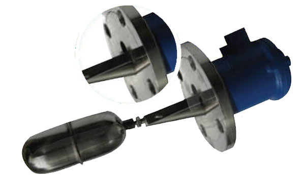
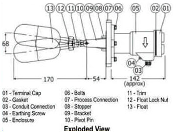
Side Mounted Magnetic Level Switch
Introduction
Side Mounted Magnetic Level Switch is an economical free and reliable device used for high, low and intermediate point level switching. It is used for tanks with inaccessible tops or bottoms and where insertion depths of top mounted models exceeded.
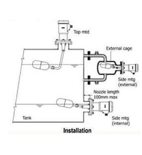
PrincipleThe Side Mounted Magnetic Level Switch has a compact & rugged construction, consisting of a free moving pivoted float assembly and a switch enclosure in non magnetic material to achieve undisturbed magnetic flux. It employs dual magnetics, one carried by the float arm and other by contact carries housed in switch enclosure. A change in liquid level brings the like poles of dual magnets opposite to each other and resulting repulsion force ensures a changeover of contacts with snap action. The magnetic transmission is glandless, leaving no scope for leakages from vessel into switch housing. These switches are manufactured in various materials, enclosure and special features to suit broad range of media and applications. They are designed to provide high repeatability and to minimise effects of shock, vibration and pressure.
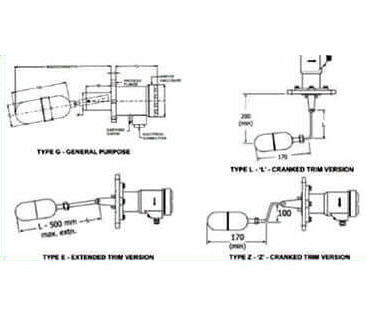
Type of Constructions
Specification
- Installation: Normally Side & Top Mounted for special applications
- Enclosure: Cast Aluminum
- Conduit Connection: 1/2” BSP ( F) with 1/2 “ BSP (M) conduit
- MOC of Floats: SS304, SS316, PP, SS304 with PVDF coated
- Min. Specific Gravity: 0.6 depending upon float material and dimensions
- Process connections: Flanged or screwed
- Min.Specific Gravity: 0.7 (minimum)
- Switch Type: Micro Switch ( SPDT or DPDT )
- Switch Rating: 5A/250 VAC
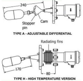
- Switch Differential: Fixed ( 10 +- 5mm) Adjustable between 40 & 300mm depending upon float, trim length cam positioning.
- Accuracy: +-12mm
- Reapeatability: +-1mm
- Max.Operating Temperature: Upto 250 °C and High temperature model up to 350 °C Max.Operating Pressure: Upto 20 Kg/cm2 at ambient temperature (Consult factory for pressure more than 20 Kg/cm2)
- Special Features: Adjustable differential, L/Z cranked trims, High temp, Construction with radiating fins
- Ingress Protection: IP 65
- Float Diameter: 45mm (48 mm at welded seam)
- Insertion Depth: 215 mm (Standard)
Mini Level Switch
Introduction
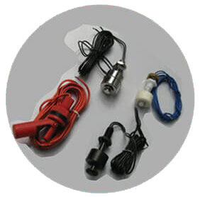
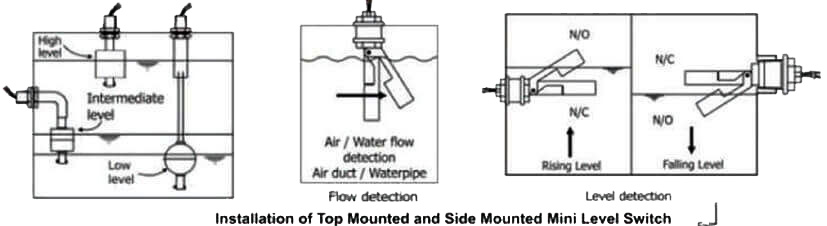
The PI Controls Mini Level Switches are top mounted as well as side mounted. Top Mounted mini level switches are installed vertically and can be extended through an extension pipe for low level switching or alternatively switch can be side mounted through an elbow. The switch action can be changed from N/O to N/C and vice versa by simply reversing the float direction. The Side Mounted mini level switches are installed horizontally and can be mounted vertically for some applications like flow detection. The switch action can be reversed by reorientation of the mounting.
Principle
Top Mounted Mini Level Switch
The top mounted Level Switch has a simple & sturdy construction, consisting of a float and guide tube, made of nonmagnetic material to achieve un-disturbed magnetic flux. The float has a magnet system within it and moves freely along the guide tube which contains glass encapsulated hermetically sealed reed switches located at present positions. Float flows liquid level and magnetically actuates reed switch at preset positions to gives change over contact. Single swicthing is available through single float depending float size and switch construction. It can be mounted vertically from top and can be extended through an extension pipe for low level switching or alternatively switch can be mounted through an elbow.
Side Mounted Mini Level Switch
The Side Mounted mini switches are installed horizontally and can be mounted vertically for some applications like flow detection. The switch action can be reversed by reorientation of the mounting. The level switch can be wired directly in series to operate electrical loads like audio or alarm, annunciation, mimic indication, which match the low sitching capacity of reed contacts. However, high loads like contractor, solenoid or motorized valve should be connected through a level controller to prevent overloading by surge or inrush current and isolate reed contacts from the electrical power system, to ensure their long life.
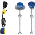
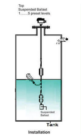
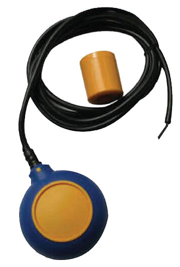
Cable Float Level Switch
Introduction
 Cable Length
The PI Controls Cable Float Level Switch is a simple user friendly and reliable switch for liquid level detection. By selecting an appropriate float and cable length, it can be used for small or long range detection of liquids, with or without impurities, sanitary applications like drinking water and also for explosive liquids or liquids in hazardous areas. Besides this by using a number of cable floats with appropriate fixation points, it can be used for multipoint detection.
PrincipleThe Cable Float Switch consist of a float, integral with a three core electric cable. A fixed micro switch and a moving steel ball are enclosed within the float casing. A change in liquid level causes the float to tilt up or down around a pivot, provided in the form of an adjustable stopper, support pipe or ballast, at an angle and in the process, actuating a steel ball to move and operate a micro switch plunger to close or open an electrical circuit with potential free contacts, to operate auxillary electrical devices like, alarm, pump and solenoid valve.
Specification
- Float Protection WP - IP-68
- Terminal Enclosure Cast Aluminum, WP IP-66
- Cable Gland Brass
- Process Connection Flanged x 1”, 1-1/2”, 2-1/2”, 3”, 4” NB, 150#
- Integral Cable Length 2,3,5,6,8,10,15 & 20 meters (Larger lengths on request )
- Contact Type Microswitch (SPDT)
- MOC of Float Polypropylene
- MOC of Counter Weight Polypropylene
- MOC of Cable Neoprene x 10 mm2
- Min. Liquid Specific Gravity 0.75
- Adjustable Stopper Polypropylene
- Support Pipe SS304 / Polypropylene
- Suspended Ballast SS304 / Polypropylene with PVC insulated SS304 rope
- Shape Disc
- Differential Angle 28
- Max. Operating Pressure 2 Kg/cm2
- Max. Operating Temperature -10 °C to 70 °C
- Switch Rating 8A, 250 VA°C
- Service Clear or Dirty Water
Basic Model
- 02 = 2 Meter
- 03 = 3 Meter
- 05 = 5 Meter
- 06 = 6 Meter
- 08 = 8 Meter
- 10 = 10 Meter
- 15 = 15 Meter
- 20 = 20 Meter
- XX = Non Standard
Orderig Example: PI0015
Note: Modifications may take place and materials specified may be replaced by others wothout prior notice
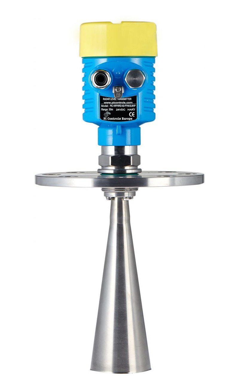
Non contact radar level Transmitter and GWR
Introduction
PI series of radar level meter adopted high frequency radar sensor, the maximum measurement range can reach up to 70 meters. ®®Antenna is optimized further processing, the new fast microprocessors have higher speed and efficiency can be done signal analysis, the instrumentation can be used for reactor, solid silo and very complex measurement environment.
Features
- 2-wire compact transmitter
- 26 GHz (K-band) measuring signal
- Non-contact level metering
- Accuracy up to ±3 mm
- Measuring range up to 23 m
- Plug-in graphic display module
- HART communication
- 99-point linearization
- Plastic, aluminum or stainless steel housing
- Stainless steel horn or plastic enclosed antenna
- High temperature range
- IP 67 protection
- Explosion-proof models
Features
Level measurement of liquids, slurries, emulsions and other chemicals Water and wastewater industry Pharmaceutical industry, chemical industry Food-industry, energy-industry For high precision level measurement tasks.
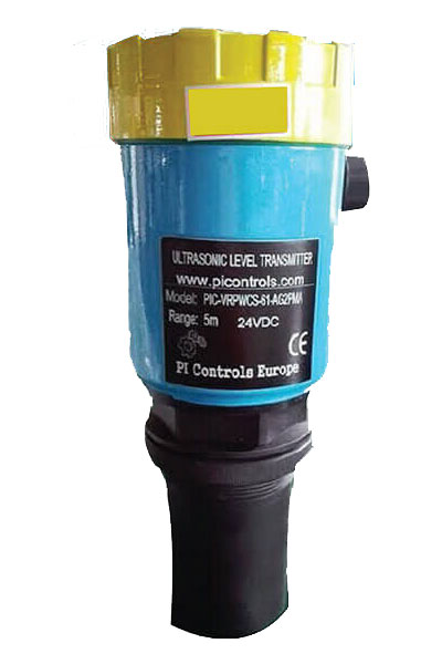
Ultrasonic Level Transmitter
Introduction
ULT for liquid level measurement in sumps or tanks, for tank contents measurement, or open hannel flow measurement, this transmitter provides the answer. Installed on the tank roof, or above the iquid surface to be measured, the transmitters give analogue output proportional to liquid level or transmit HART digital data. It is an intelligent compact ultrasonic level transmitter with 4-20 mA output offering HART protocol as option. The unit is tank-top mountable only. This is an integrated, blind transmitter with equal measuring performance but readable and programmable remotely only through HART protocol coming as standard.
Features
- 2- or 4-wire compact transmitters
- Non-contact level metering
- Narrow 5° beam angle
- Fully temperature compensated
- Excellent signal processing via QUEST + software
- PP, PVDF, PTFE, stainless steel or foam faced transducers Opional field indicator and plug-in programmer/display
- Optional switching relay
- Built-in Data Logger
- Plastic or Aluminum housing
- [ HART]
- Secondary lightning protection
- Explosion-proof models
Application
Almost any liquids Level, volume and open channel flow measurement Reliable measurement in challenging applications such as vapour/fume, stirrer, foam with liquids®
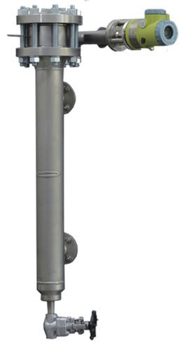
Smart Displacer Level Transmitter & Controller
Smart Displacer Level (Interface) Transmitter
ZTD series smart displacer level (interface) transmitter (hereinafter called ZTD) is joint manufactured by PI Controls Ltd and Fisher Controls Company. ZTD-G is multi-purpose transmitter designed for measuring level, interface, or density. Having multiple function, durability, stability, and cost-effective properties, it’s welcomed by customers in petroleum line for tank, vessel or process control, etc.
Displacer Level Controller
Measuring element of displacer level controller is ball float or displacer, measuring element connected with magnet tube. When level raised, magnet tube moves up and enters external magnetic field. Through magnet induction effect or magnet coupling effect, the magnet controlling switch or offset magnet steel is pulled and makes switch contact on or off. When level goes down, the magnet tube moves down and goes out off the external magnet field. Then the magnetic controlling switch backs to the original state of the offset magnet steel goes down back to new balance position under the action of self-weight, and then makes switch contact on or off. In this way, it realizes level controlling and alarming.
Industries We Serve
- Oil & Gas Sector
- Chemical Industry
- Pharmaceutical Industry
- Water Treatment Industry
- Paper Pulp industry
- Fertilizer Industry
- Food Processing Companies
- Engineering Works
- Fabricators
- Shipbuilding & Marine
- Steam & Power Generation
- Refrigeration & Air Conditioning