
Pipe Lifting Clamp.
Lifting Cap. Per Pair in Tons |
Jaw Opening (mm) |
Plate Thinkness (mm) |
2 |
35 |
16 |
3 |
40 |
20 |
5 |
50 |
25 |
10 |
60 |
36 |
20 |
75 |
45 |
Lifting Clamp Series
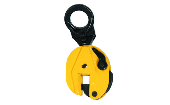
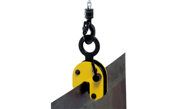
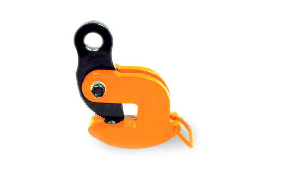
Vertical Steel Plate Lifting Clamp
Application : Lifting and Transporting steel plate vertically.
Range of working load : 1-16 T. One clamp is used in the tests but in real cases two or more clamps are recommended. Only one layer of late being lifted each time. Lifting more than one layer of plate is prohibited. The steel plate being lifting shall be kept away from crashing on any other objects. When lifting the steel plate, the handle must be turned up and turned down when unloading. The tested loads of DSQ 1, DSA2, DSQ3 & DSQ5 are all 2 times of working load limit, the minimum breaking load is 4 times of the working load limit.The tested loads of DSQ8, DSQ12, DSQ16 are 1.5 times of the working load limit, the minimum breaking load is 3 times of the working load limit.
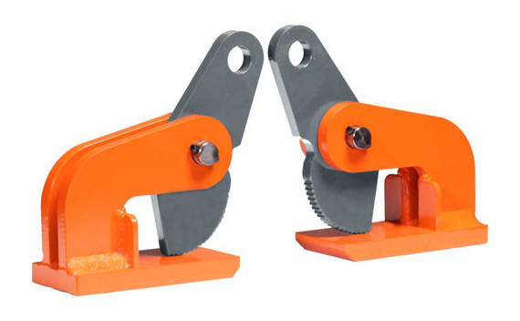
Horizontal Steel Plate Lifting Clamp
This clamp is designed to lift and transport steel plate horizontally. Range of working load : 2 ‐ 10 T. Two clamp are used in the tests, but in real case four clamp are recommended. The levering beam is needed when the steel plate is too long Test loading is 2 times the Working Load Limit. Minimum breaking Load is 4 times the Working Load Limit.
Vertical Steel Plate Lifting Clamp
Art |
WELL t |
Tickness mm |
A mm |
B mm |
C mm |
D mm |
E mm |
F mm |
G mm |
H mm |
I mm |
Jaw open mm |
NW kg/pc |
DSQ1 |
1 |
0-16 |
59 |
12 |
16 |
45 |
30 |
120 |
72 |
270 |
155 |
50 |
3.5 |
DSQ2 |
2 |
0‐22 |
61 |
16 |
23 |
55 |
45 |
165 |
90 |
340 |
190 |
55 |
6.3 |
DSQ3 |
3 |
5‐30 |
72 |
16 |
28 |
60 |
55 |
195 |
110 |
374 |
227 |
370 |
10.5 |
DSQ5 |
5 |
16‐55 |
82 |
20 |
33 |
70 |
70 |
250 |
135 |
458 |
275 |
90 |
19.3 |
DSQ8 |
8 |
40‐80 |
100 |
25 |
40 |
80 |
80 |
345 |
175 |
565 |
370 |
130 |
40 |
DSQ12 |
12 |
50‐90 |
107 |
28 |
45 |
90 |
105 |
430 |
182 |
635 |
380 |
150 |
52 |
DSQ16 |
16 |
60‐100 |
107 |
41 |
50 |
100 |
115 |
455 |
200 |
650 |
410 |
160 |
55 |
Horizontal Steel Plate Lifting Clamp
Art |
WLL t/2 |
Tickness mm |
A mm |
B mm |
C mm |
D mm |
NW kg/pc |
DSQ2 |
2 |
0-20 |
127 |
154 |
58 |
29 |
2.6 |
DSQ3 |
3 |
0-30 |
152 |
187 |
64 |
31 |
4.0 |
DSQ5 |
5 |
20-60 |
220 |
289 |
70 |
54 |
7.8 |
DSQ8 |
8 |
50-100 |
276 |
369 |
86 |
59 |
15.7 |
DSQ10 |
10 |
60-125 |
310 |
432 |
86 |
61 |
19.5 |